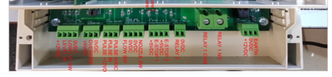
2.3 Fuellox Wiring
TerminalsLink
2.3.1 Mains Power – 12VDCLink
J3 Pin 1 - 12v DC JS
Pin 2 - 0V DC
2.3.2 Pump Switch RelayLink
J19 Pin 1 - Pump Active (12v DC – Max Load 30A) J19
Pin 2 Pump - Active (12v DC – Max Load 30A)
2.3.3 Pulse Meter – ReedLink
J5 Pin 2 - Signal
J5 Pin 3 - 0v DC
2.3.4 Pulse Meter – Hall Effect from Fuellox PowerLink
J5 Pin - 1 5V DC
J5 Pin 2 - Signal
J5 Pin 3 - 0v DC
Hall effect meters can be powered from alternative power sources at times.
Note
Please discuss alternative wiring options with the Fuellox Team to ensure your warranty conditions.
2.3.5 Terminal DiagramLink
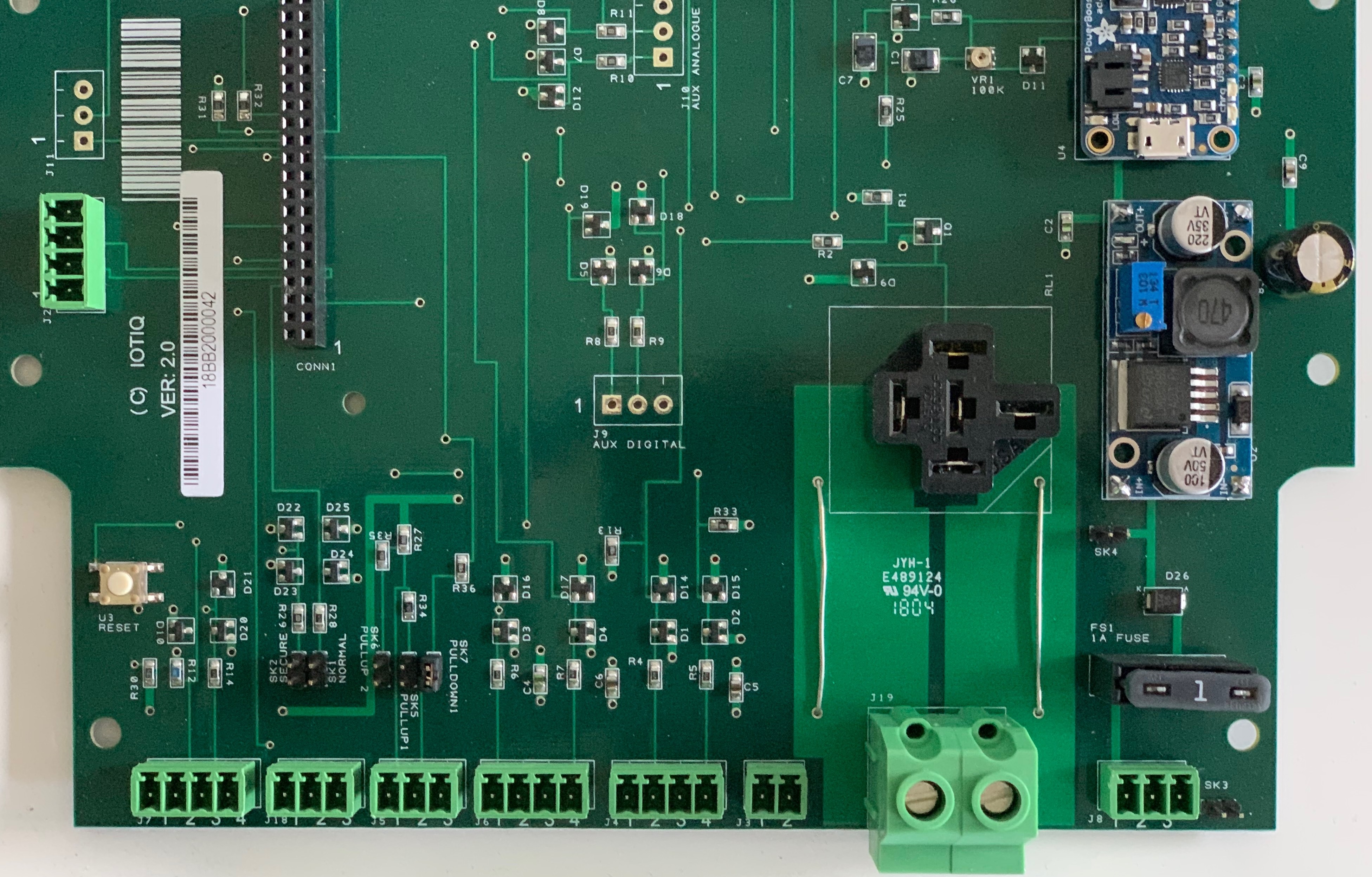
2.3.6 Terminal DiagramLink
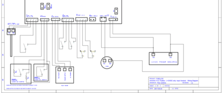
A wiring diagram is available : Fuellox Wiring Diagram Right click and Save As to download or click to open in new tab.
2.3.7 Wiring DiagramLink
Note
All input but Estop 1 and 2 are held high by internal pull-up resisters on Arduino and are pull low by external devices, thus active low. Estops 1 and 2 are pulled low thus active low needs to be held high by external devices.
2.3.8 Wiring diagramLink