2.4 Meter Wiring
2.4.1 Macnaught MetersLink
There are several types of Macnaught meters.
We have had superior results with MX range of meters.
Most Macnaught meters and registers come with Pulse, or Hall Effect as:
-
Either of
-
Both Of
-
Dual
Where odd behavior is detected or low quality signal/noise from the meter output, it may need to use a combination of the pullup/pulldown resistors built into the Fuellox design.
2.4.2 kFactorsLink
Machanught usually calibrates the meter and publishes its kFactor in the format of Pulses per Litre.
To calculate the Fuellox kFactor simply divide 1 by the published figure and enter the resulting kFactor to 6 decimal places.
On occasion further calibration may not be required.
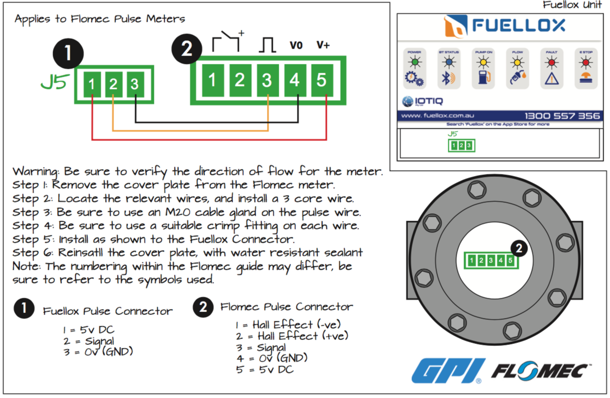
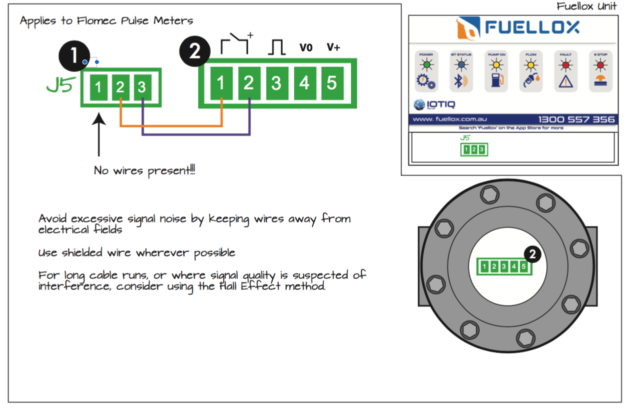
2.4.3 Wiring GuideLink

2.4.4 Flomec MetersLink
Flomec meters may also present as GPI branded meters.
2.4.5 Gespasa MetersLink
We have had limited success with Gespasa meters at this point and until further integration testing they are not recommended or supported.
2.4.6 Liquip MetersLink
Liquip meters are mostly found on bulk dispensing pumps such as Ebs Ray, Alfons Haar etc.
You will generally find they are used in mobile applications but sometimes in large off-road refuelling facilities such as mines, tank farms and for very large machinery refueling.
Fuellox integrates positively with these meters where an operator can actuate the pump via the Fuellox relay.
Where an Electronic Register is used, see Section 2.4.7
Where a Mechanical Register is used, see Section 2.4.11
2.4.7 DFV RangeLink
The meter needs to have the output pulse connected, prior to calibration by the Liquip authorised agent. Electronic Pulse out, to Fuellox J5, Pins 2 & 3 as per typical pulse meter reed type installations.
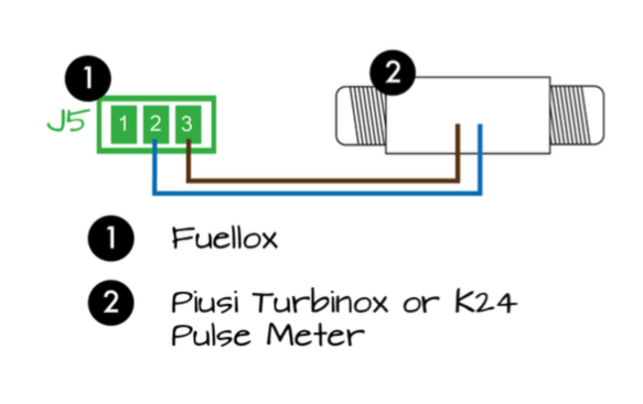
2.4.8 Piusi MetersLink
Piusi meters mostly come with a Reed effect, in 2 wire format.
Piusi Reed SwitchLink
Piusi K24 and Turbinox each use a brown and blue wire. We have several units running with these meters.
2.4.9 PS100 Pulse MeterLink
Used as a meter transmitter for/with a mechanical register. The PS100 is a medium quality part imported from China. Note this meter does not include a wet seal and installation to should be completed by an experienced installer. Contact the Fuellox team for an appropriate referral from your region.
Depending on the register type it may be nesecary to discard the register, and use the shaft from the meter. Under such circumstances, ensure the meter body is sealed and that fuel can not escape the meter assembly.
Warning
Modification of any meter may result in changes to the calibration requirements, performance and repeatability.
This meter comes with dual pulse outputs, however only 1 shall be used with Fuellox.
PS100 wiringLink
| PS 100 Meter | Fuellox | Description |
|---|---|---|
| Red | J8 Pin 1 | +12 V DC |
| Black | J8 Pin 2 | 0 V DC |
| Yellow | J5 Pin 2 | Pulse Signal |
| Blue | Exclude | Spare pulse channel |
A wiring diagram is available : PS100 Wiring Diagram Right click and Save As to download or click to open in new tab.
Installation StepsLink
- Locate the main shaft coming from the Mechanical meter register.
- Build a mounting assembly that locates the pulse meter body to the shaft position
- Build and install a shaft to match the register shaft to the pulser shaft
- Remove the wire connector and connect the cables as per above. Be sure to use shielded cable at all times
- Commission the meter and test with the Fuellox system
- Calibrate the Fuellox pulse signal to the existing meter register.
2.4.10 Macnaught MX with ERALink
The Macnaught meter can facilitate an additional display by integrating the Machanguth ERA display. Its recommended that a single meter be used where a display and pulse is required. The use of 2 meters (ie 1 mechanical and 1 digital) can lead to confusion for operators and calibration complexity.
The main signal wire enters the ERA Display and is bridged to the Fuellox
Note
Macnaught recommend a dual hall/reed type meter, however this wiring guide is for the 1RA type meters, with a sinlge Hall effect. The Reed effect is no used.
ERA WiringLink
| Power | MX-25 | ERA | Fuellox |
|---|---|---|---|
| 12V +ve | none | Pin 1 | J8 Pin 1 |
| 12V -ve | none | Pin 0 | J8 Pin 2 |
| Pulse from MX-25 | ERA |
|---|---|
| Green | Pin 9 |
| Yellow | Pin 10 |
| Red | Pin 11 |
| Blue | Abandon |
| White | Abandon |
| ERA | Fuellox |
|---|---|
| 5 | J5 Pin 3 |
| 6 | J5 Pin 2 |
Several configuration steps are required to ensure the ERA displays correctly. When stuck, consult the Macnaught service team, during business hours via the head office technical team.
Detailed ERA Wiring Diagram Right Click and 'Save As'
ERA ConfigurationLink
The ERA display can be difficult to set up with the Fuellox system. Go through the ERA Menu and adjust each parameter as follows. Macnaught ERA Manual Right Click and 'Save As'
| Section | Setting | Context | Value |
|---|---|---|---|
| 1 | TOTALS | ||
| 1.1 | Units | Display units | L |
| 1.2 | Decimals | Decimal places on display | 0 |
| 1.3 | kFactor | Litres per pulse, from calibration certificate | See Meter documentaion |
| 1.4 | Decimal kFactor | Decimal places in kFactor | 6 |
| 2 | FLOWRATES | ||
| 2.1 | Units | Display units | L |
| 2.2 | Time | Time display for flow rate | |
| 2.3 | Decimals | 222 | |
| 2.4 | kFactor | See 1.3 | |
| 2.5 | decimals kFactor | 6 | |
| 2.6 | Calc/pulse | 10 | |
| 2.7 | cut off | 30 | |
| 3 | DISPLAY | ||
| 3.1 | Function | total | |
| 3.2 | Light | 100 | |
| 4 | POWER MANAGEMENT | ||
| 4.1 | LCD New | 1 sec | |
| 4.2 | Batt Mode | OP | |
| 5 | FLOWMETER | ||
| 5.1 | Signal | NPN LP | |
| 6 | ANALOGUE OUTPUT | Leave as default | |
| 7 | IMPULSE | ||
| 7.1 | Pulse Width | Output signal width | 0.01 |
| 7.2 | Decimals | decimal places of Impulse settings | 3 |
| 7.3 | Amount | vol per pulse | 0.027 |
| 8 | COMMUNICATION | Leave as defaults | |
| 9 | OTHERS | Meter Parameters |
2.4.11 Veeder Root 7671 family of pulsersLink
Veeder Root pulsers operate a hall effect. Fuellox requires a single channel pulse from the 7671. Veeder Root also offer a family of meters that integrate directly with the pump. These 3 channel meters are not suitable for use diretly with Fuellox.
In some circumstances the 7671 can suffer from noise interferrance, such as when used in a confined space with a large 3 phase motor and pump. In these cases additional wiring is required.
Wiring DiagramLink

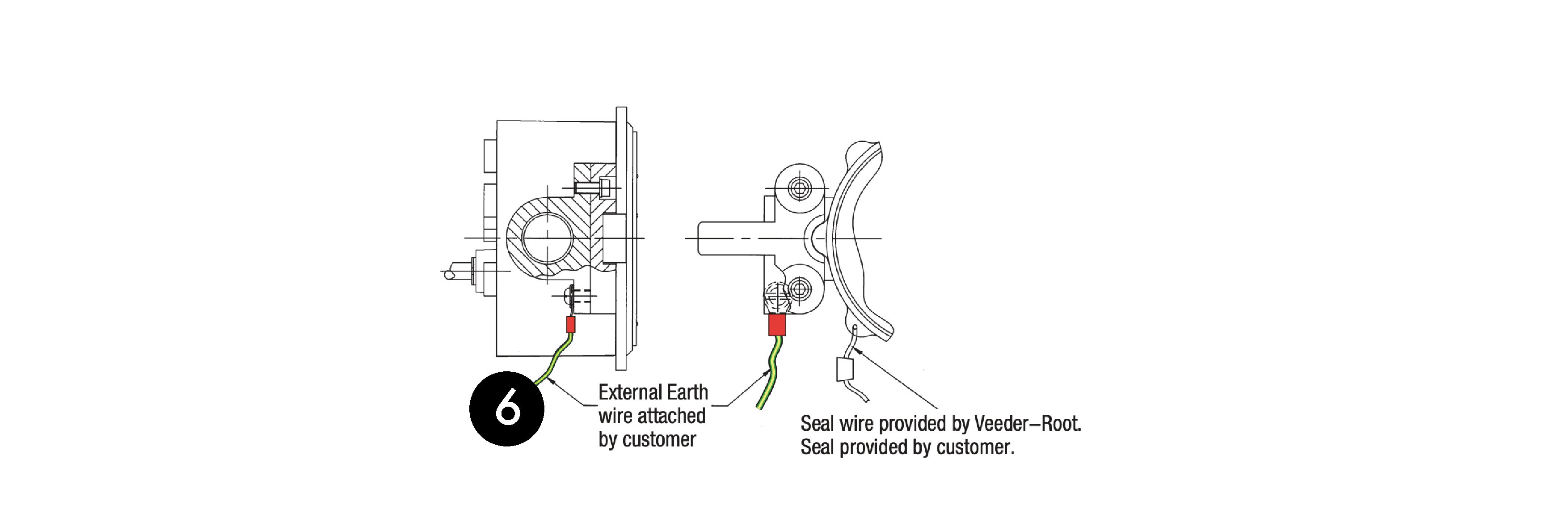
Earthing of MeterLink
The Veeder Root pulser must also be grounded as per the OEM directions
Jumper settingsLink
Apply jumpers to SK5 and SK7 for this meter type. See Pull up & Pull down resistors.
Wiring detailLink
| Item | Part | Label | Pin | Description |
|---|---|---|---|---|
| 1 | Fuellox | J5 | 1 | Meter Power 12V DC |
| 1 | Fuellox | J5 | 2 | Meter Signal |
| 1 | Fuellox | J5 | 3 | Meter 0V (Floats) |
| 2 | Fuellox | J3 | 2 | Wire shield to 0V DC |
| 3 | VR 7671 | - | GND | to Fuellox J5-3 |
| 3 | VR 7671 | - | CH 1 | to Fuellox J5-2 |
| 3 | VR 7671 | - | V+ | to Fuellox J5-1 |
| 4 | Shielded Cable | - | Cable | 3 Core, MUST be shielded |
| 5 | Shielded Cable | - | Shield | 3 Core, MUST be shielded |
| 6 | VR 7671 | Earth | 3/16 screw | Suitable Earth to ground stake |
Pulse meter configurationLink
7671 meters will produce either 10, 50 or 100 pulses per Litre and depends largely on the configuration of the mechanical meter, and pump type.
Start with a device kFactor of 0.1 and calibrate against the mecahnical meter. Ensure the meter register has been calibrated by an authorised service technican. Note: Once the Mechanical meter has been calibrated the Fuellox system should not need to be recalibrated. The relationship to meter revolutions should be maintained.
Cable recommendation:Link
We have had excellent results with Jaycar 4 Core, Screened Cable Part WB1540. Where a screened cable is not used, system reliability and accuracy is not assured. Warranty does not apply for incorrectly installed meters.
2.4.12 Other MetersLink
We can and will test other meter integrations only where our technical team can access the hardware units for testing.
Alternatively you can lone or provide free issue samples to the Fuellox team for evaluation and testing. Costs may apply.