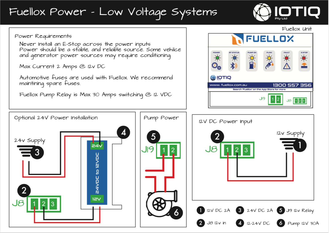
2.2 Power Source
2.2 12V DC Electrical InstallationLink
2.2.1 System PowerLink
Fuellox requires a 12V DC 1 amp supply. Fuellox will run from automative circuits, and batteries.
2.2.2 Pump PowerLink
Fuellox can switch a 12V DC pump up to 30Amps peak load.
For higher loads a higher current relay will be required.
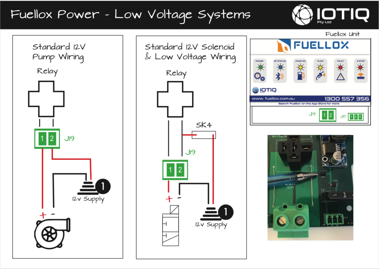
2.2.2 Low Voltage System DiagramsLink
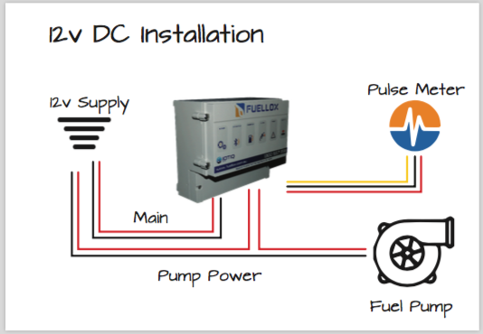
2.2.3 12V DC Installation DiagramLink
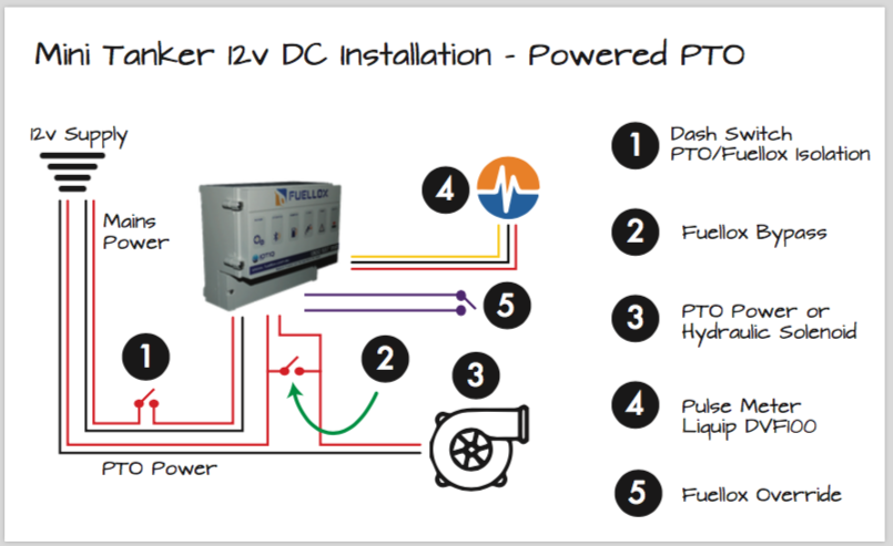
2.2.4 12V Powered PTO Installation DiagramLink
2.2.5 24V DCLink
Fuellox can be ordered with a 12V-24V power adapter, or then be simply installed in the field when needed.
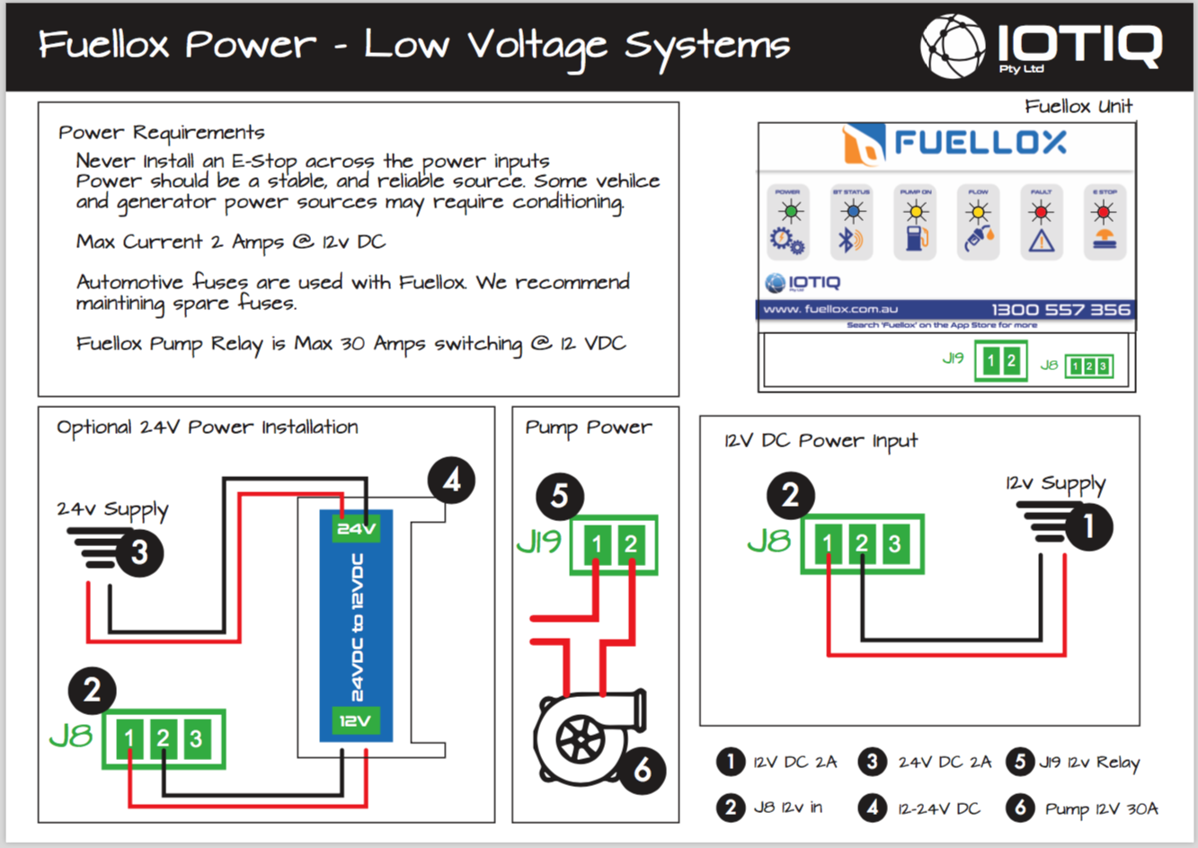
Note
The parts supplied convert mains 24V DC to 12V DC to suit Fuellox. It does not convert the Fuellox relay switch to 24V DC.
We recommend the installation of an automotive style 12V DC to 24V DC relay. ie a 12V coil and a 24V relay.
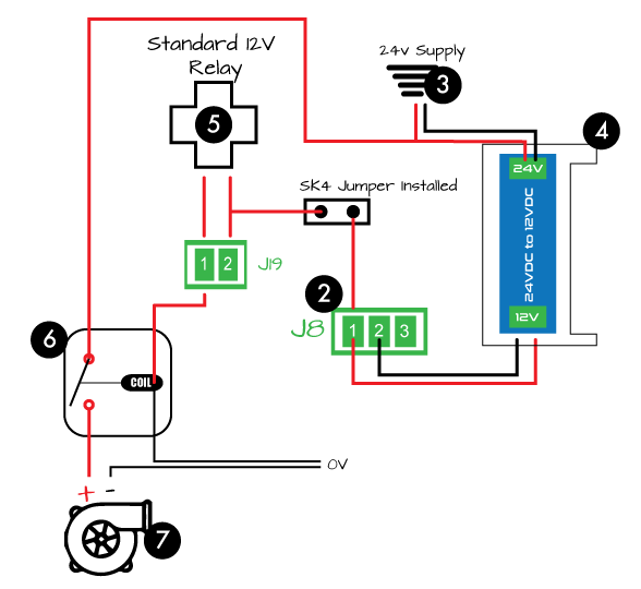
| Point | Name | Description |
|---|---|---|
| 2 | J18 | Fuellox 12V DC Input |
| 3 | 24V | Vechilce Power Supply (24VDC) |
| 4 | 12-24V | 12-24V DC Power conversion board |
| 5 | Switch | Fuellox Main Relay (12V DC Only) |
| 6 | Relay | 12V Coil 24V power relay, automotive style |
| 7 | Pump | 24V Pump or solenoid, depending on pump type |
2.2.6 240V AC Electrical InstallationLink
Fuellox can work from mains 240V AC power. Simply add the expansion module to operate from mains power, and switch a 240V AC pump.
Danger
240V AC systems must be installed by a licensed electrical contractor.
Alternatively source the components and have an electrician complete the installation.
The drawings suplied in 2.2.7 and 2.2.8 assume the recommneded Fuellox parts have been acquired from your supplier.
2.2.7 240V AC Installation DiagramLink
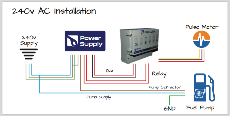
To order a 240V AC expansion module, please call the Fuellox team or your Fuellox supplier.
2.2.8 240V AC Wiring DiagramLink
Detailed Electrical Diagram Right Click and 'Save As'
2.2.8 415V 3 Phase Electrical InstallationLink
Work in progress. Please contact he Fuellox Team for more information on 1300 557 356
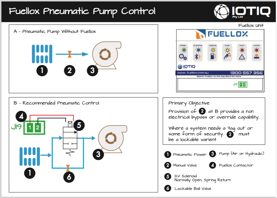
2.2.9 Pneumatic Control/Installation DiagramLink
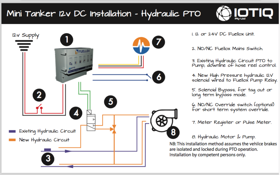
2.2.10 Hydraulic PTO 12V InstallationLink
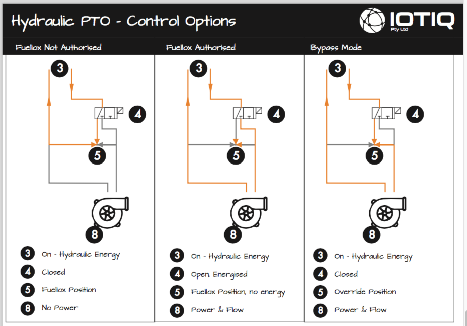
2.2.11 Hydraulic PTO Control OptionsLink
| Item | Part | Description |
|---|---|---|
| 3 | Hydraulics | Ensure all components installed meet or exceed the pressure rating of the max hydraulic output pressure. |
| 4 | Solenoid | A Three Port 2 Position Solenoid is required. Spring return is also required to ensure valve closure when de-energised. |
| 5 | Ball Valve | A 2 position 3 port L type ball valve is recommended. Use a lockable valve and padlock to ensure no unathorised persons can bypass the system. |
| 5* | Ball Valve Location | Locate the valve discreetly if you need to, however locate it in an obvious position if you need a 'tag out' option. |
| 8 | Pump | Do not switch the PTO as other hydraulic components will inly operate when the Fuellox unit is Authoirsed. |