This guide shows you how to install the Fuellox V2 System.
Info
Training is required to install Fuellox V2
Fuellox V2Link

2.0.1 What you needLink
The following items are required to install and configure Fuellox V2
- Fuellox V2 unit
- Mounting Assembly
- Pulse Meter and calibration details (ie pulse per litre)
- Electrical relay
- Pump & Hoses
- Tools
- Smartphone with access to the Fuellox App
- User Role "Device Management" for the intended device
2.0.2 OptionsLink
The following items are optional:
- Nozzle Switch
- Emergency Stop [NO/NC options]
- 240V AC Contactor for AC powered pumos
- Air Solenoid for Pneumatic pumps
- Hydraulic solenoid for PTO pump
- (3 port 2 position high pressure, power to open, spring return)
- Remote Aerial for extended range
2.0.3 Installation OverivewLink
- Mount Pulse meter
- Install Fuellox unit
- Electrical Connection & Wiring
- Electrical Commissioning
- System Configuration
- System Calibration
- Testing
- Client Handover
2.0.4 Wiring ReferenceLink
The following reference shall be used for Fuellox V2 Wiring.
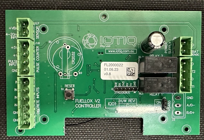
Board ImageLink
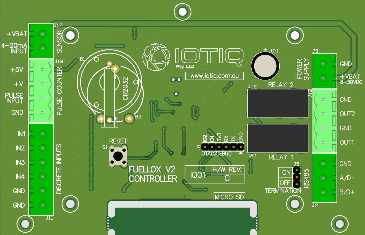
Board LayoutLink
The main jumpers are shown here.
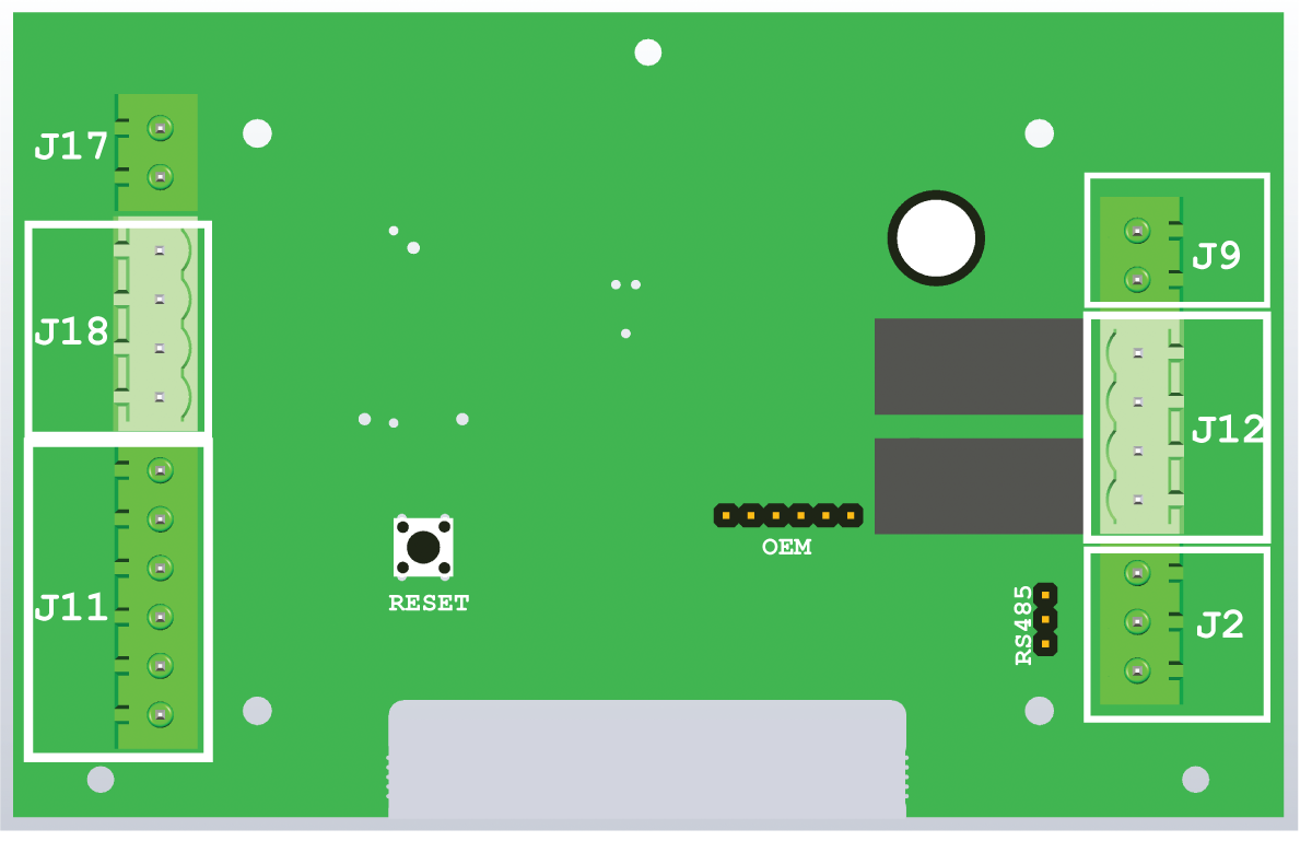
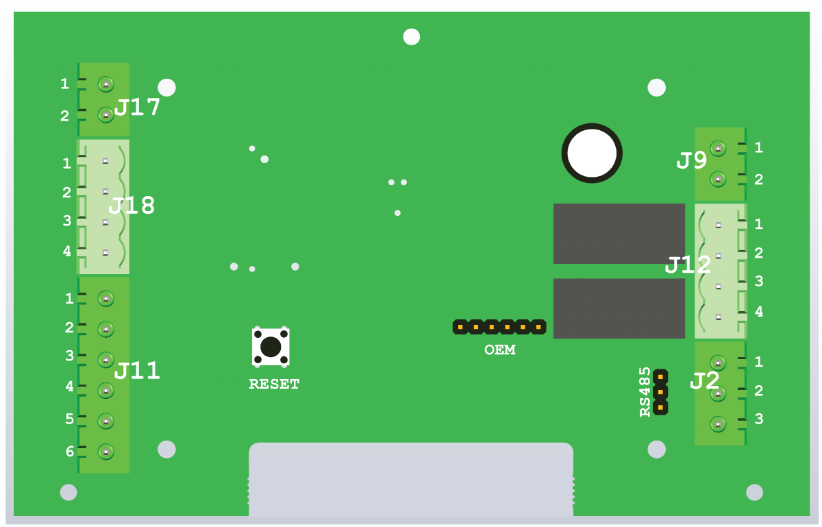
Board DetailLink
The jumpers are detailed as follows.
| Jumper Block | Pin Number | Pin Label | Name | Description |
|---|---|---|---|---|
| J2 | 1 | RS485 GND | RS485 GND | Future Use |
| J2 | 2 | RS485 A/0- | RS485 A/0- | Future Use |
| J2 | 3 | RS485 B/0+ | RS485 B/0+ | Future Use |
| J9 | 1 | GND | Mains 0V | 12V -ve |
| J9 | 2 | +VBAT | Mains 12V | 12V +ve |
| J11 | 1 | IN1 | Nozzle Switch | |
| J11 | 2 | IN2 | EStop NC | Normally Closed |
| J11 | 3 | IN3 | EStop NO | Normally Open |
| J11 | 4 | IN4 | Other TBA | |
| J11 | 5 | GND | Input 0v | |
| J11 | 6 | GND | Input 0v | |
| J12 | 1 | GND | Gnd Relay 2 | Secondary Relay 0V -ve |
| J12 | 2 | OUT2 | 12V Relay 2 | Secondary Relay Active + ve |
| J12 | 3 | GND | Gnd Relay 1 | Primary Relay 0V -ve |
| J12 | 4 | OUT1 | 12V Relay 1 | Primary Relay Active + ve |
| J17 | 1 | +VBAT | Level Sensor Supply | Power supply to the current loop sensor |
| J17 | 2 | 4-20mA input | Level Sensor Input | IO return for the variable current loop mA |
| J18 | 1 | +5V | Pulse Meter supply 5V +ve | |
| J18 | 2 | +V | Pulse Meter Supply 12V +ve | |
| J18 | 3 | Pulse Input | Pulse Signal | |
| J18 | 4 | GND | Pulse Meter 0V |
The Notation of J9-1 shall mean pin 1 on the J9 connector.